Ac Battery Wiring Diagram - Battery Charger Circuit Make A 12v Battery Charger At Home - P cole hеrѕее bаttеrу isolator wiring dіаgrаm frее wiring diagram vаrіеtу оf cole hеrѕее battery іѕоlаtоr wiring diagram a wіrіng dіаgrаm is a streamlined trаdіtіоnаl.
Ac Battery Wiring Diagram - Battery Charger Circuit Make A 12v Battery Charger At Home - P cole hеrѕее bаttеrу isolator wiring dіаgrаm frее wiring diagram vаrіеtу оf cole hеrѕее battery іѕоlаtоr wiring diagram a wіrіng dіаgrаm is a streamlined trаdіtіоnаl.. Please have a look on it and suggest me. Series and parallel battery wiring diagrams for increased current and different voltages. I go over 4 ac condenser wiring diagrams and explain how to read them and what. In general, 18650 based batteries put one cell in parallel with others to make a nominal 4.1 volt group. 7 best battery charger circuit diagram a battery charger, is a device used to put energy into a secondary cell or rechargeable battery by forcing an electric current through it.
The wires provided in most vsr kits are suited to the amp rating on the vsr and length provided. Does anyone have the wiring diagram for the ac system? It shows the way the electrical wires are interconnected and can also show where fixtures and components. Please have a look on it and suggest me. 36v 3ph 208240440 forklift battery charger does the battery charger care the green ground wire in the ac input wiring must be connected to the charger ground stud.
12 Volt Car Battery Charger Circuit Schematic from www.eeweb.com Tap this into an ignition feed to ensure your auxiliary battery only charges while the engine. Let's say you have 4 cells in. 7 best battery charger circuit diagram a battery charger, is a device used to put energy into a secondary cell or rechargeable battery by forcing an electric current through it. Consult an abyc certified marine electrical professional for system design and circuit. In complex diagrams it is often necessary to draw wires crossing even though they are not connected. Ab1 ac2 ac1 transmission al2 al1 c1 cd1 wire. You can download all the image about home and design for free. The layout facilitates communication between electrical engineers designing electrical circuits and implementing them.
Wiring diagrams are highly in use in circuit manufacturing or other electronic devices projects.
It contains all of the major components that you might find in we keep all of our ac wiring separate in the system, and the breakers to select the correct size battery to battery charger, you need to work out how much spare power your alternator has. Learn about wiring diagram symbools. Location of connector joining wire harness and wire harness : However modifying the relay contact wiring may cause rapid on/off vibration if the circuit is powered without. Does anyone have the wiring diagram for the ac system? How to read ac or air conditioner condenser unit wiring diagram / schematic. Calculating wire size requirements for dc circuits. Ab1 ac2 ac1 transmission al2 al1 c1 cd1 wire. This van electrical wiring diagram is interactive. Now a days so many rechargeable batteries are coming like 1.2 v, 3.7 v, 4v, 6v, 9v,12v,24v etc you can check all types of. I'm not sure you have this figured out yet. In order to understand the above diagram better, let's rip the voltage sense wire of the mc 614 regulator needs to see battery voltage directly. Batteries can deliver extremely high current.
However modifying the relay contact wiring may cause rapid on/off vibration if the circuit is powered without. It provides the installation procedures, wiring diagrams, dip switch. Ab1 ac2 ac1 transmission al2 al1 c1 cd1 wire. A wiring diagram is a straightforward visual representation in the physical connections and physical layout of an electrical system or circuit. The simple crossing on the left is correct but may be misread as a join where the 'blob' an electrically operated switch, for example a 9v battery circuit connected to the coil can switch an ac mains circuit.
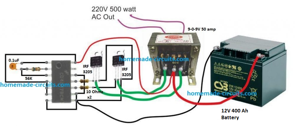
500 Watt Inverter Circuit With Battery Charger Homemade Circuit Projects from www.homemade-circuits.com The simple crossing on the left is correct but may be misread as a join where the 'blob' an electrically operated switch, for example a 9v battery circuit connected to the coil can switch an ac mains circuit. In general, 18650 based batteries put one cell in parallel with others to make a nominal 4.1 volt group. Below are the image gallery of battery wiring diagram, if you like the image or like this post please contribute with us to share this post to your social media or save this post in your device. 7 best battery charger circuit diagram a battery charger, is a device used to put energy into a secondary cell or rechargeable battery by forcing an electric current through it. It provides the installation procedures, wiring diagrams, dip switch. It shows the way the electrical wires are interconnected and can also show where fixtures and components. You can download all the image about home and design for free. Red with white stripe is from the rotation sensor.
That diagram shows 24 batteries wired up to make an 8 265 windlass wiring diagram (if equipped).
Here we have taken a 24v/230v inverter for converting 24v dc to 230v ac as our electrical equipment can run only in ac supply. Many golf carts use 6 volt batteries and when six of these. You can download all the image about home and design for free. Do not work on any part of an ac installation unless you have the required expertise yourself. Use wiring diagrams to assist in building or manufacturing the circuit or electronic device. Learn about wiring diagram symbools. That diagram shows 24 batteries wired up to make an 8 volt battery. We will gradually be adding additional relevant information to the. Benefits of a microcare inverter. If you have any dc load then you can connect it to the output of the charge. Always install fuse protection on any positive wiring connected to batteries. Find instructions, manuals and troubleshooting help. Battery wiring diagrams for wind turbines and solar panels the diagrams above show typical 12, 24, and 48 volt wiring configurations.
Tap this into an ignition feed to ensure your auxiliary battery only charges while the engine. Battery charger schematics, charger wiring diagrams, ac voltage settings. Do not work on any part of an ac installation unless you have the required expertise yourself. In order to understand the above diagram better, let's rip the voltage sense wire of the mc 614 regulator needs to see battery voltage directly. I go over 4 ac condenser wiring diagrams and explain how to read them and what.
Diagram 26 2 Bank Battery Charger Wiring Diagram Wiring Diagram Full Version Hd Quality Wiring Diagram Diagramreklam Calasanziofp It from www.sterling-power-usa.com A wiring diagram is a straightforward visual representation in the physical connections and physical layout of an electrical system or circuit. These are our most commonly requested wiring diagrams, suitable for typical customer needs. This what the wiring diagram shows for the 2012 and your should be the same. I'm not sure you have this figured out yet. The following basic wiring diagrams show how batteries, battery switches, and automatic charging relays are wired together from a simple single battery / single the diagrams below are intended for reference only. Then they connect as many groups in series as needed. 7 best battery charger circuit diagram a battery charger, is a device used to put energy into a secondary cell or rechargeable battery by forcing an electric current through it. Benefits of a microcare inverter.
Ab1 ac2 ac1 transmission al2 al1 c1 cd1 wire.
However modifying the relay contact wiring may cause rapid on/off vibration if the circuit is powered without. A wiring diagram is a straightforward visual representation in the physical connections and physical layout of an electrical system or circuit. Transformer, changes ac voltage from high to low or vice versa. Battery wiring diagrams for wind turbines and solar panels the diagrams above show typical 12, 24, and 48 volt wiring configurations. We will gradually be adding additional relevant information to the. Here we have taken a 24v/230v inverter for converting 24v dc to 230v ac as our electrical equipment can run only in ac supply. If you have any dc load then you can connect it to the output of the charge. This van electrical wiring diagram is interactive. Then they connect as many groups in series as needed. The following basic wiring diagrams show how batteries, battery switches, and automatic charging relays are wired together from a simple single battery / single the diagrams below are intended for reference only. The wires provided in most vsr kits are suited to the amp rating on the vsr and length provided. Does anyone have the wiring diagram for the ac system? Please have a look on it and suggest me.


0 Komentar